Inspiration
I stumbled upon a gift shop hidden at the very tip of Cape Cod based entirely on upcycling. They had items such as notepads made of old floppy disks, wallets constructed from tin can tabs, and PCB accessories. One of the PCB accessories was two halves of a heart, which I, an electrical engineer, thought is a perfect gift for another electrical engineer who has significance in your life. But what if I could make it even more meaningful? I asked my electrical engineering partner to join me on this quest.
Planning
Our goal for this project was to create two halves of a heart with LEDs that light up in a pattern only when the halves are connected.
It would be battery powered to avoid the hassle of having to plug it in to a power source. Additionally, we wanted each half to be an appropriate size for a keychain, around 2" X 2".
Schematic and PCB Layout
With a clear image of our final product, we were able to quickly put together a schematic in Altium. See the full schematic here.
While designing the PCB layout, I learned a useful trick for working with multiple boards at once. I created the first board shape of half a heart, then created a mirrored version of the first board and used Altium’s panelization to see the two halves together, while keeping them fully separate.
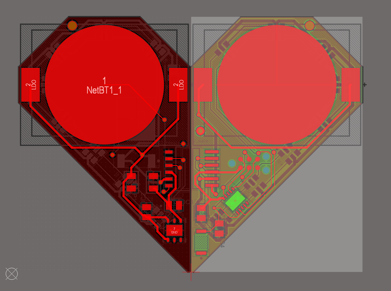
This was especially important for lining up the pin headers, so the resulting heart would fit together smoothly
See the complete PCB layout here.
Assembly
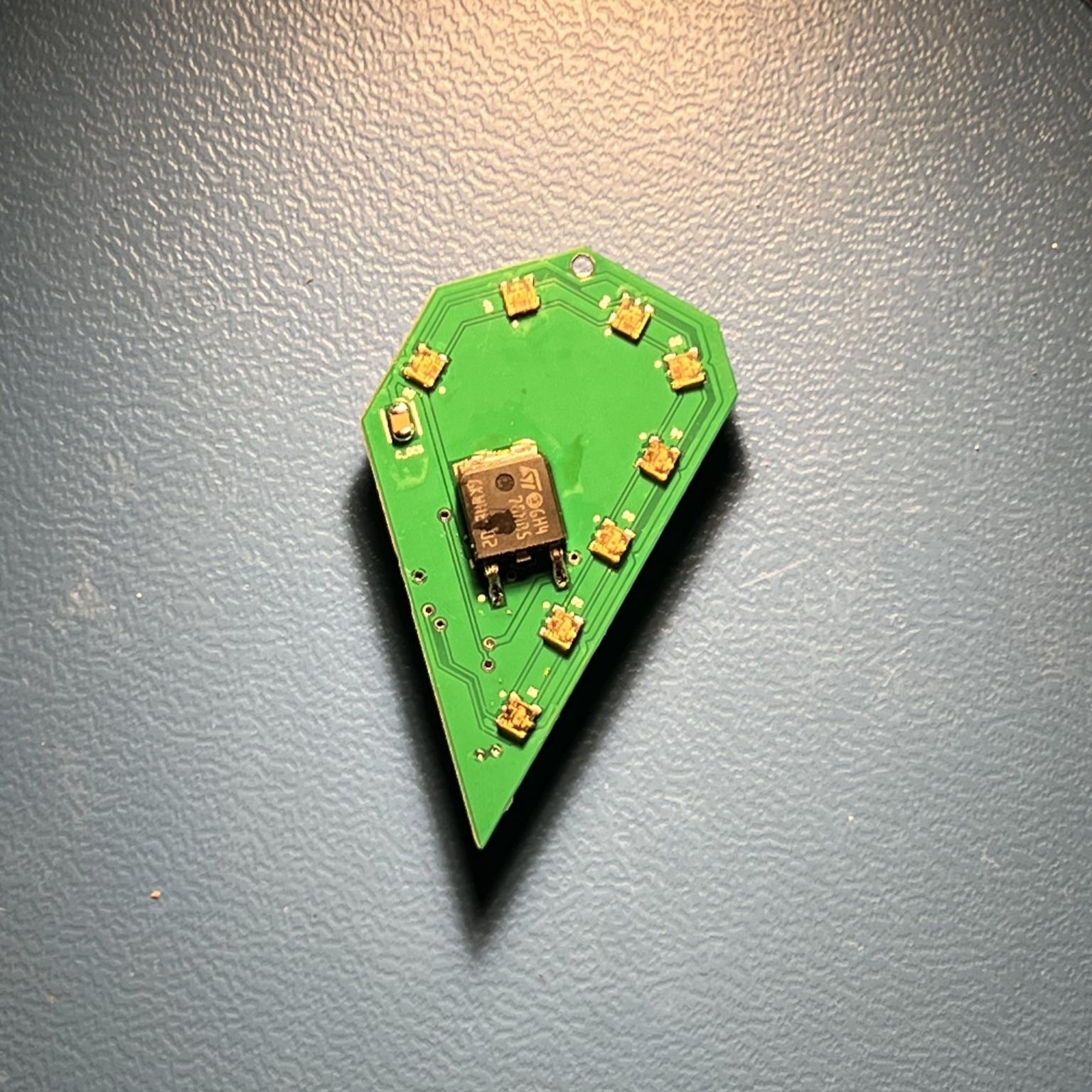
This is how the hardware turned out after soldering all the components to the board.
 Left back side of keychain | 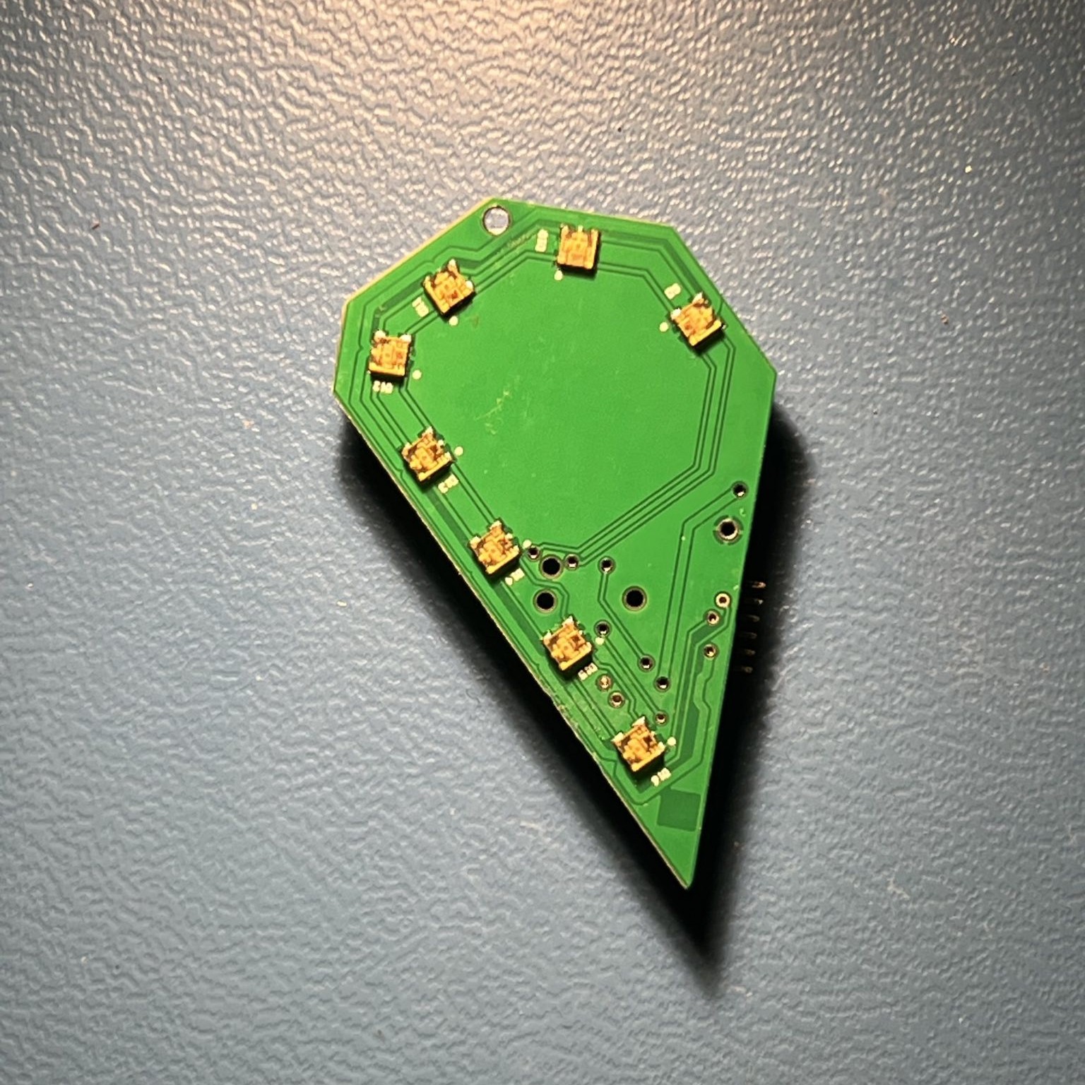 Right back side of keychain |
|---|---|
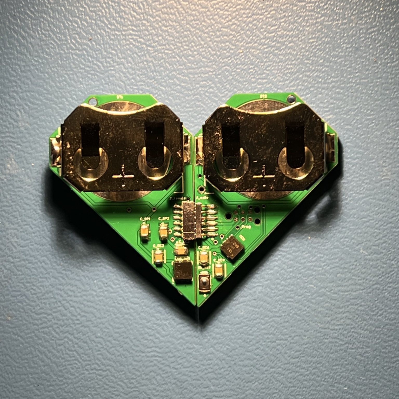 Top side of keychains connected | 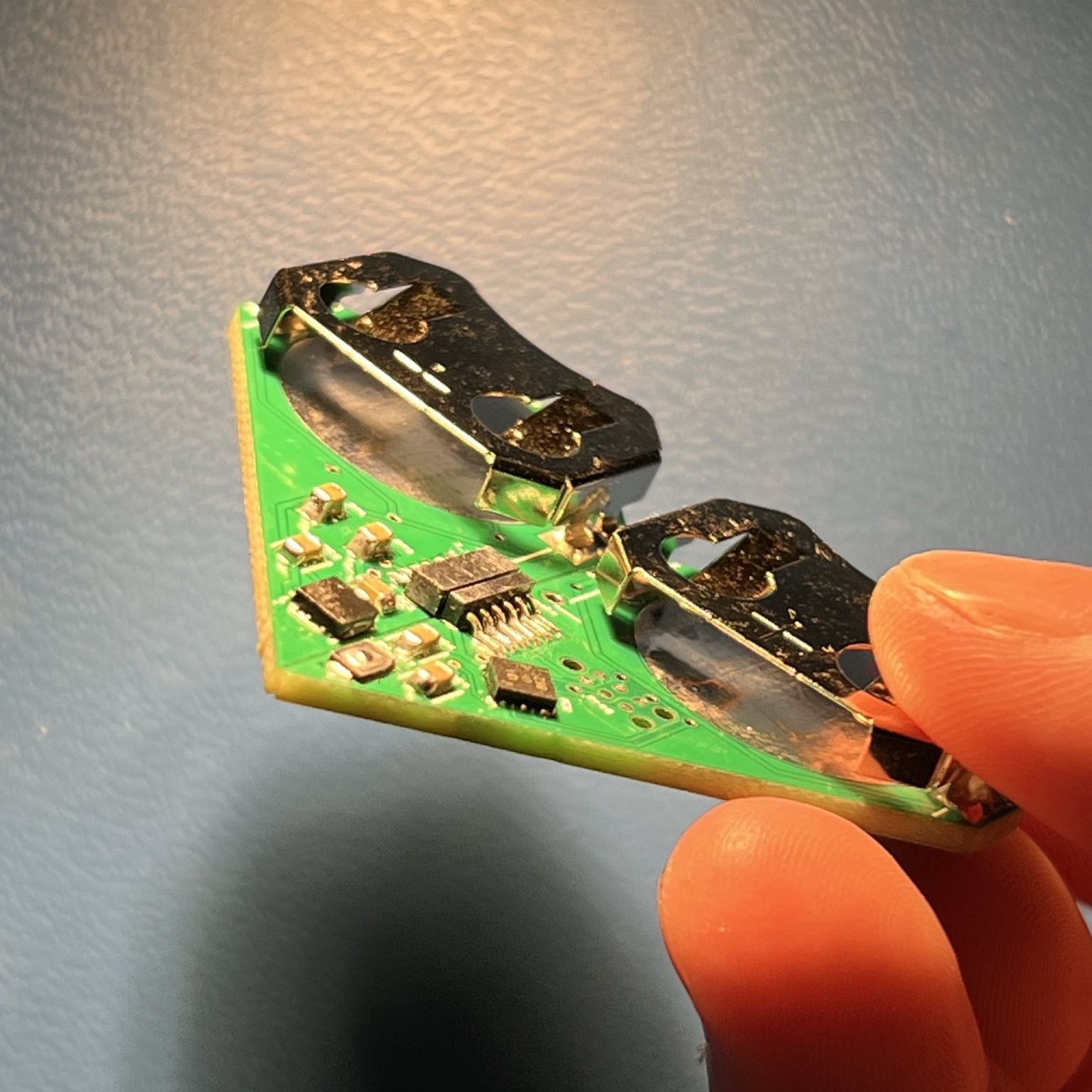 Top side of keychains connected, held at an angle |
Firmware
Our final step is to complete the firmware for the keychain. Because we had a very restrictive size constraint, we had to be creative finding a way to program the microcontroller. We originally hoped to use a USB-C port, but realized it would be far too big. So we decided to use the Tag-Connect TC2030 to communicate with the microcontroller. This process involves connecting the connector to an Arduino Uno, then connecting the Arduino to the microcontroller, ultimately using the Arduino as a programmer. Our preliminary goal is to get the LEDs to illuminate in any specified pattern. Our future goal is to be able to control the lights with external inputs, such as a heart rate detector. Stay tuned for updates on this project!